ISSN 1884-0760
GRACE TECHNICAL REPORTS
A Novel Approach to Goal-oriented Adaptation with
View-based Rules
Tianqi Zhao Tao Zan Haiyan Zhao
Zhenjiang Hu Zhi Jin
GRACE-TR 2016–01 February 2016
CENTER FOR GLOBAL RESEARCH IN
ADVANCED SOFTWARE SCIENCE AND ENGINEERING NATIONAL INSTITUTE OF INFORMATICS
A Novel Approach to Goal-oriented Adaptation
with View-based Rules
Tianqi Zhao* Tao Zan+
Haiyan Zhao* Zhenjiang Hu*+ Zhi Jin*
*Institute of Software, School of EECS, Peking University Beijing, 100871, China
zhaotq12, zhhy, [email protected] +National Institute of Informatics
The Graduate University for Advanced Studies 2-1-2 Hitotsubashi, Chiyoda-ku, Tokyo 101-8430
zantao, [email protected]{hu,kato}@nii.ac.jp
June 12th, 2009
Abstract
Rule-based adaption provides a powerful mechanism to program adaptable software, where rules specify adaptation logic of what particular action should be performed to react to monitored events. It has advantages of readability and elegance of each individual rule, the efficiency of plan process, and the ease of rule modification. However, adaptation rules in the existing approaches are not structured well, which makes it difficult to deal with efficient conflict resolution, to be seamlessly combined with user’s goal and requirements, and to evolve dynamically. In this paper, we propose a novel idea ofνRule for structuring adaptation rules. The structured adaptation rules are expressive enough for programming intended adaptation logic, and their well-behavedness that is automatically checked at the design time can guarantee that they will not lead to any conflict at runtime. In addition, we show thatνRule provides a flexible mechanism for users to customize and evolve the adaptation systems. We have designed and implemented a new view-based adaptation framework for supporting construction of adaptive systems, based onνRule and the feature modeling technique, and successfully apply it to realize a nontrivial smart home system.
1
Introduction
rule-based adaptation system, a set of adaptation rules are used to specify adaptation logic of what particular action should be performed to react to monitored events.
Typically, an adaptation rule takes the form of “condition ⇒ action” where
conditionspecifies the trigger of the rule, which is often fired as a result of a set of monitoring operations, andactionspecifies an operation sequence to perform in response to the trigger. For instance, in a smart room system (as will be explained more in Section 2), we may have the following rule
Light.Power =off ∧ Time=daytime
⇒Blind.State :=open; Window.State:=open
which declares that if the light is power off in daytime, then open the blind and the window. Obviously, rule-based adaptation has advantages of readability and elegance of each individual rule, the efficiency of plan process, and the ease of rule modification.
In spite of these advantages, adaptation rules pay attention only to local trans-formation, which makes it difficult to satisfy user global goal that expresses the purpose of the developed system. Moreover, like the operating context, user goal setting may change dynamically, and good self-adaptive systems should be flexible to adapt accordingly without intervention from technicians. However, the adaptation rules are static so that the adaptation logic defined by the rules cannot change at runtime, which prevents it from being adaptable to dynamic goal change.
On the other hand, the goal based and utility function based approaches [5, 6] provide a solution to make adaptation plans that can match with changed goal. They normally reduce the dynamic adaptation as a linear programming problem and leave the system to reason on the actions required to achieve high-level goals or optimize utility functions. While, despite a greater possibility to find an optimized solution at runtime, they always encounter large resource consumption and suffer from high execution cost.
In this paper, we propose a novel approach to enriching rule-based adaptation with goals bystructuring adaptation rules withinvariant. The key idea is to (1) refine the rule by splitting the condition part into two asview∧condition ⇒action, whereview denotes aninvariantthat will be preserved after the action, and (2) impose the following semantics to the rule: “Underview, ifconditionis satisfied,
doactionwhile keeping theview.”
The important point is the use of invariant for capturing the view state that a rule should maintain in adaptation. Since a user goal is usually realized by a (proper) state [5], it is this view state that enables us to associate rules with goals. To make theview stand out in the rule, we shall write the rule as
view ⊢condition⇒action
and call it view-based rule (νRule for short) in this paper.
• We present a novel concept ofνRule , where an invariant view is introduced for structuring adaptation rules and relating them with goals (Section 3.2). As a refinement of the traditional adaptation rules,νRule s are expressive enough for programming intended adaptation logic. On the other hand, thanks to more refined structure and added invariant semantics,νRule s serve effectively as basic units for construction of various powerful and well-behaved adaptation rule systems at both design and run times.
• We propose a new view-based adaptation framework for supporting construc-tion of adaptive systems based onνRule and the goal-oriented modeling technique (Section??). It seamlessly integrates the rule-based planning with the goal-based planing, gaining the advantages of both traditional rule-based and goal-based adaptation approaches. Accordingly, the run-time adaptation can efficiently response to the changes in both the environment and the user goal setting.
• We have implemented the framework1with two newly developed algorithms (Section??). One is for goal-based planning where we introduceproperty
to bridge the gap between goals and features and divide the optimization procedure into two steps: goal-based reasoning in section 3.4.1 and strategy derivation in section 3.4.2. The other is for dynamic rule generation, where by use of the good connection between the goal-related feature view and the νRule structure, a well-behaved goal-relatedνRule set is dynamically derived from theνRules in the static knowledge base.
We have applied the framework to design a smart room system. Our experimen-tal results (Section??) show that (1) our approach reaches a much higher degree of goal satisfaction than the traditional rule-based adaptation approach; and (2) our approach scales and works more efficiently than the traditional goal-based approach.
2
Running Example: Smart Rooms
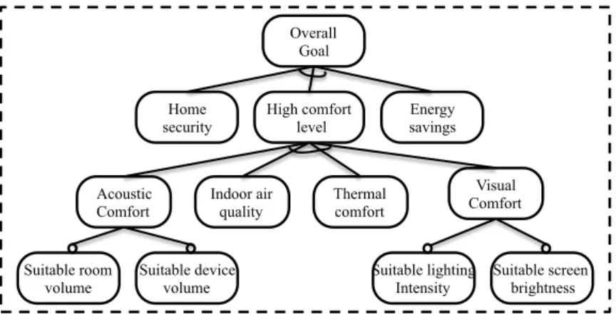
Let us imagine such a typical scenario: developers want to construct a smart home for its residents as shown by the goal model [7] in Figure 1. A smart home system is usually designed under three main concerns: it should reduce energy consumption, provide a high level of resident comfort and ensure home security. In the literature of smart home [8], thermal comfort, visual comfort and good air quality are regarded as three basic factors that determine the quality of life in buildings. Besides, different smart home system take some more factors into account, for example, acoustic comfort. These factors can be treated as goals that adaptive system should satisfy.
An example of dynamic adaptation to meet the goalssuitable lighting intensity
andsuitable screen brightnessare as follows. A computer with adaptive capacity can adjust itself to indoor lighting intensity. When the residents modify computer
1
Energy savings High comfort
level
Thermal comfort
Visual Comfort Indoor air
quality Home security
Overall Goal
Acoustic Comfort
Suitable lighting Intensity
Suitable screen brightness Suitable room
volume
Suitable device volume
Figure 1: A Goal Model for Smart Home
screen brightness, this modification should be kept to make the user feel that he has full control of the room. At the same time, if there comes a request ofsuitable light intensityfor the room, it should give several possible resolutions to the request, such as, turning on the light, opening the blind or both of them.
The adaptation mechanism in a smart home system should not be immutable, rather, the mechanism itself should also be adaptive to user goals, priority of goals, and user preferences. This is because that different residents might pay their attention to different goals according to their interests. Generally, a self-adaptive system could well adapt itself to dynamic changing environment without human intervention. However, for a smart home, its resident may need to have a full control of all the home states, and have the permission to add new devices and new rules into the adaptation engine.
It is, however, not easy for the developers to build such a smart home system that meets all these requirements. To set the smart room developers free from this tough task, it will be helpful to have a new framework to facilitate them to construct such kinds of smart home system in an easy way like following: 1) formalizing the smart home context, including the physical environment, the devices and their reconfigurable parameters, by the feature modeling technique; 2) specifying adaptation logic by a set of adaptation rules that associate with user goals. With these two kinds of information, the new framework will generate automatically an adaptation engine for the smart home system.
The following characteristics are desired for the new framework:
•Free from conflicts. As long as the adaptive rules provided by the developer meet the standards of our framework, possible conflicts of these adaptive rules would be detected statically and there will be free from runtime conflict. Therefore, there is no need to bother the residents of smart home to resolve on-line conflicts.
Executor Check validity(C)
Automatic generation(D.1)
Analyzer/Planner
Monitor
Context(physical environment and software) Monitored
CFM
Plan in CFM Rule based Adaptation engine
(D.2 and D.3)
vRules(B)
CFM(A)
Customized slicing CFM
Goals priority User goals
Goal related rules
Figure 2: Overview ofνRule-based Adaptation Framework
mechanism that links the capability of monitoring the context and the capability of reconfiguring the devices .
•Integration of human preference. Once the user modifies the states or proper-ties of certain devices, the modification would be preserved, and not at the expense of sacrifice other selected user goals.
•Easy for evolution.It will be free for the user to add new features or new rules into the adaptive engine. The new added rules can be validated and added into the original rules set in a conflict-free way.
3
ν
Rule-based Adaptation Framework
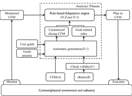
To establish aforementioned framework in Section 2, we propose aνRule-based adaptation framework, which is depicted in Figure 2. The adaptation cycle follows the traditional MAPE-K Loop [4], which stands forMonitor,Analyze,Planand
Executebased on aKnowledge base.
While, the improvement of our framework is the knowledge base. We distinguish two knowledge bases in this framework, i.e., the static knowledge base that is built in the development time and the dynamic knowledge base that is dynamically constructed in terms of the static knowledge base according to the current user goal setting. Owe to the characteristics ofνRule that will be detailed in Section 3.2, the
Planpart has the capability of combining the rule-based plan and the goal-based plan together. So, the run-time adaptation can response the changes in both the environment and the user goals.
It basically follows the traditional MAPE loop of a dynamic adaptive system [4], consisting of monitor, analyzer, planner and executor.
3.0.1 Monitor and Executor
The monitor is realized by a set of sensors, which is, for example, to collect physical information such as outside temperature and room properties as well as information of devices in the smart room. According to the results of the monitor, the context (model) will be configured with specific values to form the monitored context (model), which would be further used by Analyzer and Planner to make a plan. The executor is to enforce the plan derived from Planner to implementation through the architecture level.
3.0.2 Analyzer and Planner
The adaptation engine in our framework plays the role of analyzer and planer in the MAPE loop in the sense that it filters and analyzes information given by the monitored context and work out an adaptation plan in the requirements. Our framework generates the adaptation engine automatically by a three-step process that integrates user goals and adaptation rules together.
3.0.3 Static Rule Checking
Our framework is equipped with a validity checking mechanism that guarantees the well-structuredνRules free from the possibility of conflicts, and the validated rules will be further used for generation of conflict-free adaptation engines.
In the rest of this section, we will elaborate the core of our framework: (A) context feature models to capture running contexts, (B) formal definition of view-based adaptationνRules, (C) the static rule validity checking algorithm, and (D) generation of adaptation engine, as denoted in Figure 2.
3.1 Context Feature Model
For an adaptive system, its context consisting of the dynamic changing physical environment, and all the devices and applications running in the environment.
We employs feature model in our framework to depict and specify the context under consideration and establishes the context feature model (abbr. to CFM). Feature models have been adopted due to the following two reasons:
• First, feature models provide intuitive ways to express variation points and constraints, and widely adopted as variability management model in the literature of software product line ([9], [10]).
PhyEnv Time: tEnum Weather: wEnum Temporal Factor Context4SmartRoom Brightness :int Properties Temperature: int Light Intensity:int Devices
Window Computer Humidity: int Blind SomebodyHome :boolean State: stEnum AirCon
Power: pEnum Power: pEnum
ScreenBrightness :int Volume:int
Properties Power: pEnum Properties
Temperature
:int Mode: mEnum Volume:
int
State: sEnum Season: sEnum
tEnum: {daytime, night}
sEnum: {spring, summer, autumn, winter} stEnum:{open, close}
pEnum:{on, off}
wEnum:{sunny, rainy, windy, snowy, cloudy} mEnum:{cooling, heating}
Figure 3: Context Model
expressed in feature model to a corresponding one in the architecture ([12], [13]).
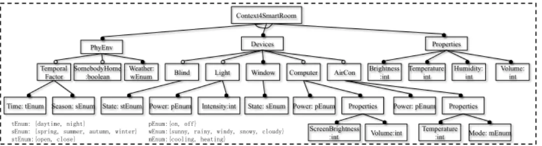
Figure 3 shows a feature model for the context of a smart home system, in which, features are hierarchically organized in a tree-like structure through refinement relationship, optional feature is denoted with a small white circle on top of the feature, whereas mandatory features with a small black circle on top of the feature. A feature is mandatory if it must be selected whenever its parent is selected.
For the smart home system, its context is comprised of the physical environment and all devices equipped in this home. The physical environment consists of
temporal factor, weather factor, user presence and room properties. temporal factorfurther includestimeandseason, whereasroom propertiesincludesvolume,
brightness, humidity andtemperature. These features could be configured with various values monitored from the sensors. Considering the featuretemperature, its value could be one collected by a thermal sensor which reflect the current temperature. Different from these features with continuous values, some features can only have enumerated states. For example,seasononly has four possible values:
spring, summer, autumn and winter, Which can also be specified as sub features of
season.
Another source of the contextual information is from devices. To each device, all the other devices can be regarded as its context, and its corresponding feature model is only a subtree in the whole context feature model.
This whole context feature model represents all the possible states of the smart home system. A legal configuration of the feature model, consisting of a set of selected features and their relationship, describes a valid state of the context. For example, the features set ofcontext, external environment, temporary factor, time, day, user presence, weather, sunny, room, light intensity, electric poser, other devices, light, power on, blind, open, describes a valid state of the whole smart home. Once certain features are reconfigured, the context state will migrate from one to another.
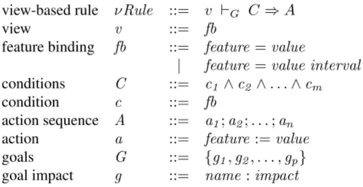
3.2 νRule: View-based Adaptation Rule
observable state view (v) of a component (device, environment), a conjunction of conditions (C), an unordered sequence of actions (A), and a set of tagged goals (G). The concrete syntax ofνRule is shown in Figure 4.
view-based rule νRule ::= v ⊢G C⇒A
view v ::= fb
feature binding fb ::= feature=value
| feature=value interval
conditions C ::= c1 ∧c2 ∧. . .∧cm
condition c ::= fb
action sequence A ::= a1;a2;. . .;an
action a ::= feature:=value
goals G ::= {g1,g2, . . . ,gp}
goal impact g ::= name:impact
Figure 4: Syntax ofνRule
TheνRule rule shows that if a component is of a statev, an actionAshould be taken under the conditionC for the purpose of G and preservation of state v. f bis called feature binding which has two alternatives: feature can be either assigned with avalue or avalue interval. For example, Light.brightness = 20 means the brightness of the light is 20, Light.brightness = (10, 30] equals to 10 <Light.brightness≤30. Each actionais a non-incremental assignment which assigns a constantvalue to afeature. Each rule is bound with a list of goals. The
impact for each goalgspecifies the actual effect for the specific statev. Let us give
aνRule example:
(R4)Light.Power =off ⊢{sl :−5,es : +3}
Time=daytime ∧Blind.State=close
⇒Blind.State :=open; Window.State:=open
R4 declares that (1) if the light is power off, for the purpose of “suitable lighting” (sl) and “energy saving” (es), we should open the blind and the window if it is in daytime with the blind being closed. (2) the fact of the Blind and the Window are open implies the fact of the light is off in daytime and the blind is closed implies that someone is at home.
Generally, theνRule implies that the component state is a representativeview
of a system state (after adaptation), which will be thus calledview-basedadaptation rule.
The point is the use of the idea of “view” in the rule specification. Rather than showing how to propagate changes (out), the new rules specify how a component state can be achieved (in) through changes of necessary components.
not weaken the expressiveness ofνRule as a rule with ac1 or c2 condition equals to twoνRules with conditionsc1andc2separately.
Jf =valK = {(f,val)}
Jf ∈ivalK = {(f,ival)}
Jf :=ivalK = {(f,ival)}
Jc1∧c2 ∧. . .∧cmK = Jc1KUJc2KU. . .UJcmK
Ja1;a2;. . .;anK = Ja1K
U
Ja2K
U . . .U
JanK
Figure 5: Representation ofνRule.
Even though theνRule is easy for developer to write view-adaptation rules, in order to clarify properties ofνRuleclearly, we interpretνRuleusing sets as shown in Figure 5. A feature bindingfbis represented as{(f,val)}which means the status of featuref isval. The operatorU
is the same as set union except that when a feature appears in both, they will be merged in the way of: (1) if the value of both arevaland equal, then either is ok; (2) if the value of both areival, the common interval are chosen as the result; (3) if one is avaland another is aivaland theval belongs to theival, then thevalis the union result.
Definition 3.1(Invariant ofνRule). AνRulev ⊢G C ⇒ Ais invariant if the state ofvis preserved after execution. That is, let{(f,val)}=JvK. For each (f′,s) ∈JAK, iff =f′, thens∈val.
Note thatsis always a value, whilevcan be either a value or value interval. For simplicity, it is considered as a special case of value interval which has only one value whenvis a value.
If a ruler is invariant, the observable statevshould be compatible with the actionAunder a conditionC. Thus the rule R4 described before shows that under the goal of “suitable lighting” (sl) and “energy saving” (es), both blind and window are open implies the light is power off.
In other words, actions inAshall not change the state ofv. For example, the following rule is not a proper view-based update rule.
(R5)Light.Power =on ⊢{sl : +5}
Time=daytime ∧Blind.State =open
⇒Light.Power :=off
The light is on, while according to the condition that if it is daytime and the blind is open, an action of power off will be done. This violates the definition of well-behavedness ofνRule, even though the rule itself makes sense. We could rewrite this rule to a proper one by considering blind as the view:
(R5’)Blind.State=open ⊢{sl : +5}
Time=daytime ∧Light.Power =on
Lemma 3.2(Rule Stability). Letrbe a correct view-based adaptation rule,mbe a feature model andr(m)means executing ruleron feature modelmresulting in a new feature model. We haver(r(m)) =r(m). We call such ruleris stable.
This means using the same rule to consecutively update feature modelmtwice shall be the same as that of updating only once which is obvious since (1) each actionais atomic and assigns a value to the feature. (2) executing an actiona twice acts as only once asJa;aK=JaK, so we haveJA;AK= JAK. The stability of a rule is important for self adaptive system as any times of this rule application shall not change the system. And it is also related to goals, the contribution of twice execution of the rule for a goal shall be the same as once.
Compared with the traditional rules, the view-based adaptation rules have the following characteristics:
• It is simple and expressive: view is constructed with a single feature from the whole context feature model, which reduces the design complexity of rules for developer. And a bigger and complex view can be constructed through production of simple views.
• It is invariant and stable: these two properties are important for simplifying validity checking. EachνRule is associated with one or more goals which are used for goal-based optimal rule selection.
3.3 Rule Validity Checking
In the previous section, we have discussed the invariant and stability ofνRule. In this section, we will give an algorithm for checking the well-behavedness (will be shown later) of the whole rule set.
Definition 3.3(Order Independence). Let ri, rj be two differentνRules,m be a feature model. Rulesri andrj are said to be called order independent if the execution result ofrifollowed byrj on the modelmis the same asrjfollowed by
ri.
If two rules are order independent, their effects on features are either none-overlapped or the same. For a set of rule R, we say it is confluent if the execution result of all rules in R is always the same regardless how they are applied. The stability ofRmeans twice execution ofRis the same as only executed once.
Theorem 3.4(Well-behavedness). LetRbe a finite set of rules,riandrjare two rules inR,i6=j. If the following two conditions are satisfied: 1. each ruler is stable; 2. rules inRare order independent.Ris confluent and stable.
This theorem is easy to prove by induction on the size ofR.
Validity checking of rules contains two aspects: a) stability of rule set R;
Ras it is implied by stability of each rulerinRand order independence of all rule pairs.
The confluence ofRis done by checking whether rules inR are order inde-pendent. Thus checking all the rule pairs: if all the pairs are not conflict (order independent), the whole set of rules are not conflict (order independent). Whether a pair of rules is order independent or not is done by the following Algorithm 1.
Algorithm 1:Order Independence Checking of Rule Pair
input : rule pair (ri,rj)
output: true, or suggestion for resolving conflicts
1. representvi,Ci,Ai,vj,Cj andAjas (fvi,svi),JCiK,JAiK, (fvj,svj),
JCjKandJAjK
2.ACij=ft(JAiK)∩(ft(JCjK)∪ft({(fvj,svj)})) 3. ACji=ft(JAjK)∩(ft(JCiK)∪ft({(fvi,svi)})) 4.Aij=ft(JAjK)∩ft(JAjK)
5.case(ACij,ACji)of
(∅,∅)→checkAction(ri,rj,Ai,Aj,Aij)
(ACij,∅)→checkConsistency(ri,rj,Ai,Cj,ACij)
(∅,ACji)→checkConsistency(ri,rj,Aj,Ci,ACji)
(ACij,ACij)→
checkConsistency(ri,rj,Ai,Cj,ACij)
checkConsistency(ri,rj,Aj,Ci,ACji)
functioncheckConsistency(ri,rj,Ai,Cj,ACij){ foreachfeature elementacij ofACij do
if(value(JAiK[acij])6=value((JCjK∪JvjK)[acij])
thenoutput conflict:(JAiK[acij], (JCjK∪JvK)[acij]) suggestion forrj: (JCjK∪JvjK)[acij]}
functioncheckAction(ri,rj,Ai,Aj,Aij){
foreachfeature elementaij ofAij do if(value(JAiK[aij])6=value(JAjK[aij])
thenoutput conflict:(JAiK[aij],JAjK[aij])
suggestion forri:JCjK∪JvjK
suggestion forrj:JCiK∪JviK}
Algorithm 1 checks whether a rule pair is order independent or not. If not, it will give suggestions for resolving conflicts. The input of this algorithm is a rule pair (ri,
rj). Firstly it represents conditions and actions into sets.ACijis a set of features of
join ofAiandvj ∪Cj. If no common features inAiand (vj ∪Cj) , this means the
execution ofriwould not affect the execution ofrj, so it is the same forACji. If
bothACij andACjiis empty, we only need to check the common features inAi
andAj have no conflict by calling functioncheckAction; if eitherACij orACjiis
FunctioncheckConsistency finds out all the possibilities that an actionai in
Ai could make a conditioncj inCj become false, thus rulerj will no longer be
executed.
Let us again recall R1 and R3 shown in Introduction (Section 1) inνRule form:
(rR1) Blind.State=close ⊢{brightness:−3}
SomebodyHome =true∧Time=daytime
⇒Light.Power :=on
(rR3) Time =daytime
⊢Weather =sunny
⇒Light.Power :=off
According to Algorithm 1,JC1K={(SomebodyHome, true), (Time, daytime), (Blind.State, close)},JA1K={(Light.Power, on)},JC3K={(Weather, sunny), (Time, Daytime)} and JA3K = {(Light.Power, off)}. AC13 = ∅, AC31 = ∅ and A13 =
{(Light.Power, off), (Light.Power, on)}. Then it calls thecheckActionfunction and find out Light.Power isonin one rule andoff in another rule, thus rR1 and rR3 are conflict. We could give one possible revision of rules by restructuring rR1 and rR3 as follows:
(rrR1) Blind.State =close ⊢{brightness:−3}
SomebodyHome =true∧Time =daytime
⇒Light.Power :=on
(rrR3) Time=daytime
⊢Weather =sunny
⇒Light.Power :=off
3.4 Generation of Adaption Engine
The adaptation engine, which is used as our analyzer and planner in the adaptive system, is automatically generated by a three-step process: goal-based configuration, νRuleimplementation and reconfiguration of CFM.
3.4.1 Goal based Configuration
Step 1 takes inputs from two sources: one is from developers at the offline phase, and the other is from residents’ daily life dynamically. The first input comprises a context feature model (CFM) and a collection of validatedνRules, which we have already introduced in Section 3.1 and 3.2 respectively. The second input includes the set of customized user goals and the priority of these goals. The set of customized user goals are obtained from the user goal model, through a process of goal customization. In this example, we assume the residents has concern about goals of{energy saving (es),room brightness (rb),computer screen brightness (csb),thermal comfort (tc),home security (hs)}and no interest in goals likeacoustic comfortandindoor air quality. All the concerned goals constitute a set of customized user goals. The other dynamic input is goal priority, which reflects the relative importance of the customized user goals. The priority of user goals are expressed here using a vector of weights , each of whose values denotes how much influence the corresponding goal has on overalll user satisfaction, i.e.
{ωes, ωrb, ωcsb, ωtc, ωhs}={0.2,0.3,0.1,0.1,0.3}
User goals and goal priorities, as two inputs of this step, might change dynamically. Once either user goals or goal priorities have changed, step 1 will be performed iteratively.
Algorithm 2 realizes the function of step 1 by first picking out a collection of goal relatedνRules. For the above example, 4 goal relatedνRules in this set are as follows, and they are tagged byrb,csboresrespectively.
(GR1) Light.Power =on
⊢{rb:+3,es:−3} Time =daytime∧Weather=sunny
⇒Blind.State:=close
(GR2) Blind.State =close
⊢{rb:−2} Time =daytime∧SomebodyHome =true
⇒Light.Power :=on
(GR3) Computer.Properties.ScreenBrightness =1
⊢{csb:+1} Time=daytime∧Weather =sunny
⇒Blind.State:=open
(GR4) Computer.Properties.ScreenBrightness =1
⊢{csb:+1} Time=daytime∧Weather =cloudy
⇒Blind.State:=open∧Light.State =on
Algorithm 2:Goal Oriented Selection and Configuration
input :vRulesvRules,context feature modelCFM, customized user goalsgoals, goal prioritypriority
output: configured CFM sliceconfigured-CFMS, goal-relatedνRules
gνRules,
gνRules =∅;
features =∅;
FtoGImpacts =∅;
foreachνRuleinνRulesdo
ifνRules.getGoals()∩goals 6=∅then
gνRules =gνRules∪νrule;
νFeature =rule.getνFeature();
features =features∪νFeature;
foreach g inνRule.getGoalsdo
impact =νRule.getImapctFor(g);
fgimpact= (νFeature,g,impact);
FtoGImpacts =FtoGImpacts ∪fgimpact;
end end end
extendedFeatures=∅;
refinementRelation =∅;
foreachfeatureinfeaturesdo
fArray =CFM.getExtendedFeatures(feature);
extendedFeatures =extendedFeatures∪fArray;
refinementRelation =refinementRelation
∪CFM.getRelation(feature,fArray);
end
SFM =features∪extendedFeatures∪refinementRelation;
sogs=calOverallGoal(features,goals, priority, FtoGImpacts);
whiletime<thresholddo
foreachfeatureinfeaturesdo
currentState=feature.getState(); feature.changeState();
Sohs′ =calOverallGoal(features,goals, priority, FtoGImpacts);
ifSohs≥Sohs′ then feature.setState(currentState);
elseSohs=Sohs′ ;
Context4SmartRoom Brightness: int Properties Temperature: int Light Devices Window Computer Blind State: stEnum AirCon
Power: pEnum Power: pEnum
ScreenBrightness: int
Properties Power: pEnum Properties
Temperature: int State: sEnum
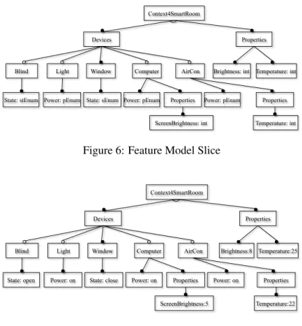
Figure 6: Feature Model Slice
Context4SmartRoom Brightness:8 Properties Temperature:25 Light Devices Window Computer Blind State: open AirCon
Power: on Power: on
ScreenBrightness:5
Properties Power: on Properties
Temperature:22 State: close
Figure 7: Configured Context Feature Model Slice
e.g. the parent featureComputerofcomputer.screenBrightness. Figure 6 is one
CFMslice for the running example. With this model slice, users can concentrate on those goal related features rather than the whole feature model, and easily determine whether the context state coincides with his or her wishes.
After having obtained theCFMS, Algorithm 2 configures it to optimize the overall goal satisfactionSogs.
sogs =
X
g∈G
Impg×ωg
=X
g∈G
( X
f∈F
Impf tog)×ωg
In this function,Impg denotes the impact for a specific goal, which is the sum
of impact from current features’ status. The configuration uses a mountain climbing algorithm to optimizesogs by callingcalOverallGoal. It keeps changing thestate
of features within a given time threshold, and callscalOverallGoalto calculate a newsogs. The change ofstate will only be accepted if it leads to a largersogs,
3.4.2 Implementation of View-based Adaption Rules
One important part of the whole view-update framework is the adaptation engine for executingνRule, which is implemented by employing the powerful bidirectional transformation languge BIFLUX [14]. BIFLUX proposed a new programming by update paradigm which is different from all existing approaches that it let programmer have flexibility to write bidirectional transformations as intentional updates, while getting bidirectional transformations for free. Since the rules are described as an update of the context feature model, the translation fromνRule to update is quite straight-forward.
The implementation ofνRule by BIFLUX including two parts: representation of a view feature model which only specifies one feature and a context feature model which includes all features monitored from Context, not only every device in the environment such as computer, TV and air conditioner etc, but also the real environment like temperature, weather and moisture; and translation ofνRules as BIFLUX updates.
The context is represented using the widely-used format XML and the document type definition language DTD for defining the data structure. All well-structured adaptive rules are translated into updates in BIFLUX. AsνRules have been
ex-plained, let us describe the translation from rule to BIFLUX update by using the rule R4 in section 3.2.
The goals suitable lighting (sl) and energy saving (es) specified in this rule have been used in section 3.4.1 for choosing a set of rules to satisfy user’s goals, thus we remove it when translating rule into update. For simplicity, we omit the definition of both source and target DTD, the XML representation of context feature model and view feature model. The translated update is shown in the following.
PROCEDURE updateFM($fm:FeatureM, $v:FeatureV) = UPDATE $fm BY {
MATCH -> REPLACE IN $fm/Devices/Blind/State WITH ’open;’ REPLACE IN $fm/Devices/Window/State WITH ’open;’ }
FOR VIEW $lightPower IN $v/Light
WHERE $fm/PhyEnv/TemporalFactor/Time = ’daytime’ and $fm/Devices/Blind/State = ’close’
and $lightPower = off
3.4.3 Reconfiguration ofCFM
Step 3 reconfigures the current context feature model. TheCFMhas been configured through monitor and filter procedure, demonstrating the information of running context in feature level. Then it is reconfigured through step 3, and the reconfigured model acts as an adaptation plan in feature level. The reconfiguration process constitutes two parts: reconfiguration based onCFMSand reconfiguration based on
vRules.
The first time of reconfiguration is based on configuredCFMSfrom step 1. This configuredCFMScomprises a collection of (feature,state) pairs to be maintained. For synchronization, features in context feature model will first be configured ac-cording to their states in the feature model slice. Through first time of configuration, goal-related features in the context feature model are configured.
The second time of reconfiguration is based onvRules. Step 1 has generated a collection of goal-relatedνRules for further rule-based adaptation. Since aνRule specifies how to maintain a state, this step will activate a subset of νRules to maintain (feature, state) pairs for goal-related features. The pair ( Computer.screen-Brightness,1) needs to be kept according to configured smart-roomCFMS, so the νRules GR3 and GR4 (shown in 3.4.1) are activated for runtime adaptation.
An activated rule will only be performed when its condition is evaluated to be true. The condition of rules are evaluated on the current configuration ofCFM. When the condition of GR3 (Time=daytime∧Weather =sunny) is true, the action part of this rule will be performed to set the state of blind open. When physical environment migrates, changes will be monitored and condition of rules will be reevaluated. Condition of GR4 (Time=daytime∧Weather =cloudy) will be evaluated to be true when weather turns into cloudy. Afterwards action part ofGR4will be performed to configure feature states.
4
User Preferences
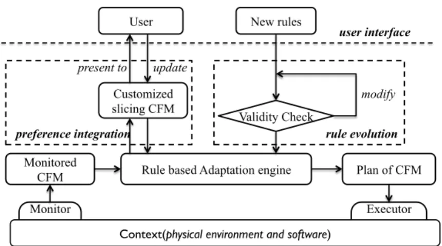
On the basis of MAPE loop, we have made two important extensions to support dy-namic user requirements. One extension is about the integration of user preferences, and the other is about the evolution ofνRules (shown in Figure 8). To integrate user preferences into MAPE loop, we provide an interface for the users to read and update. On the other hand, the users could add new rules to the set ofνRules, and validity check will be performed to eliminate conflicts.
4.1 Integration of User Preference
Executor Monitor
Context(physical environment and software) Monitored
CFM Rule based Adaptation engine Plan of CFM New rules
Validity Check
rule evolution
User
present to update
Customized slicing CFM
preference integration
modify
user interface
Figure 8: Integrate MAPE with Dynamic Requirements
the reconfiguration of some other features. Modification could be performed in two levels: feature level and architecture level.
4.1.1 Modification in Feature Level
Thefeature model slicein theadaptation engine, which consists of goal-related fea-tures and supplementary information, will be provided to users through an interface. The users can justify whether they are satisfied with the current configuration of
CFMS, and make feature level modification for personal likings. They could change thestateoffeaturef fromS1toS2if they prefer(f, S2).
Through the modification, user preferences have been integrated into the re-configured CFMS. This reconfigured CFMSwill be used for further rule-based adaptation. OurνRules have defined what(C :A)is necessary to keep a state for the view feature. Therefore,νRules which embed(f, S2)will be activated to keep the modified status for featuref.
4.1.2 Modification in Architecture Level
Our framework supports user intervention. The users could conduct modification in architecture level directly, i.e. the position of the blind, the power state of the appliances and the volume of multimedia devices.
4.2 Rule Evolution
At the run time phase, theνRules set does not stay static and it has a possibility of evolution. Since the incomplete knowledges at design phase, new features might be discovered and new rules might be added into theνRules set. Our framework has a good scalability and could well support rules evolution.
For example, there is aνRule in the set.
(R6)airCon.Power =off ⊢{es:+3,tc:−3} Temperature>27
⇒Window.State :=open
Afterwards, a new featurerainy’has been discovered on the run-time phase, and the users add aνRule related to rainy into theνRules set.
(R7)airCon.Power =off ⊢{es:+3,tc:−3} Weather =rainy
⇒Window.State:=close
When the goales ortcis customized, conflict will arise between theνRules
R6 andR7. This conflict is caused by the implement information in thecondition
part ofR6. Therefore, we modifyR6 to add additional conditionrainy.
(R6’)airCon.Power =off
⊢{es:+3,tc:−3}Temperature >27 ∧Weather =rainy
⇒Window.State :=open
This modification eliminates the conflicts between the two rules. The new νRuleR7 are added into the set, and the old oneR6 are updated and become more reasonable.
5
Threats to Validity
This section discusses some important factors that must be considered in our adap-tation framework, and potential threats that might affect the validity of our work, as well as how they are mitigated or accommodated.
5.1 Expressiveness
Threats to expressiveness involves questions of whether ourνRule-based adaptation framework is powerful enough to express any user goal driven adaptation.
evolution mechanism provided by our framework. The capability of combination and evolution of rules makes our framework be endowed with powerful expressive ability.
5.2 Construct
Threats to construct validity involve questions of whether our adaptation framework has been implemented by using adequate methodology and technology. First of all, our framework is an enhancement to the traditional MAPE-K loop approach with the view-update rules as the adaptation knowledge, and the rules can further evolve over time in response to changes in the operating context and user requirements. Moreover, our framework employs feature model to modeling and managing the commonality and variability of the domain under consideration. Feature model, on one hand, can be easily reconfigured according to different requirements and also slices according to different goals, and on the other hand, there exist relatively mature platforms ([9], [15], [16]) to support the product generation from a feature model configuration.
5.3 Applicability to Practice
We have demonstrated our adaptation framework throughout the paper using the nontrivial case of smart home system. And we are confident that our framework can be effective in any systems that can be supported by either MAPE-loop based or rule-based approaches, though we have not yet tested it with other larger cases in practice. To mitigate the threats to its applicability, we will further study in the field, and investigate more systems by equipping them with adaptation capability using our framework.
6
Related Work
constructing adaptive systems. This is a continuation of our effort in designing a powerful language to specify intentional update propagation [14].
Dynamic product line and feature models have provided new opportunity to dynamic adaptive systems. There are already some work in this area.[26] analyses commonality and differences between software product line and runtime adaptation, and gives a conclusion that it is feasible to integrate variability management in both areas. [27] introduces how to utilize parts of SPL infrastructure to adapt at runtime, and introduce that major uses of SPL in design of self-adaptive system are variability models and runtime reconfigurations.[12] [5] [13] are three important works using DSPL ideas to enable self-adaptation. They use feature models as the variability model and enable runtime reconfiguration. These work fill the gap between features and architecture by various approaches, including direct link[13], transformation rule[28], aspect model weaving and common variability language.
A lot of work uses action based rules for runtime analysis and plan ([29], [30] ,[31]), where an adaptation management system is responsible for monitoring events, evaluating conditions and initiating actions. In a rule-based dynamic adaptation system, ability to evolution is necessary to handle unanticipated situations and enhance efficiency. There are mainly two types of evolution including modifying rules and discovering new system variants. [32] which enable evolution. Our work could also well support evolution.
Our approaches are based on dynamic software product line technique ([33, 34]) and bidirectional model transformation ([35, 18, 14]) to address these issues. DPLC has provided new opportunities for self-adaptation cause it has properties of context-awareness, resource-aware decision-making, permanent service delivery, and consistent dynamic reconfiguration. There are a few researches applying DPSL techniques to support self-adaptive systems. Our approach is also based on dynamic software product line techniques and we have introduced bidirectional transformation between variability models.
7
Conclusion
In this paper, we propose a systematic view-based adaptation framework for realiz-ing more programmable and safer self-adaptive system. In our framework, rules are well structured according to each component by defining how a component state can be achieved through changes of necessary components. With the help of view-based approach, it becomes much easier to detect collision and keep rules consistent, and the detection can be conducted at design-phase statically. In order to ensure that the adaptation rules can best realize user goals, we tagged goals and impact onνRules and we use goal models as the input for generation of adaptive engine. We make an extension to support dynamic user requirements at run-time.
future.
References
[1] M. Acher, P. Collet, F. Fleurey, P. Lahire, S. Moisan, J.-P. Rigaultet al., “Mod-eling context and dynamic adaptations with feature models,” inProceedings of the 4th International Workshop Models@ run. time, 2009.
[2] N. Damianou, N. Dulay, E. Lupu, and M. Sloman, “A language for spec-ifying security and management policies for distributed systems,” London: Department of Computing, Imperial College, Tech. Rep, 2000.
[3] I. Lanese, A. Bucchiarone, and F. Montesi, “A framework for rule-based dynamic adaptation,” inProceedings of the 5th International Conference on Trustworthly Global Computing, ser. TGC’10. Berlin, Heidelberg: Springer-Verlag, 2010, pp. 284–300.
[4] B. H. e. a. Cheng, “Software engineering for self-adaptive systems,” B. H. Cheng, R. Lemos, H. Giese, P. Inverardi, and J. Magee, Eds. Berlin, Hei-delberg: Springer-Verlag, 2009, ch. Software Engineering for Self-Adaptive Systems: A Research Roadmap, pp. 1–26.
[5] J. Floch, S. Hallsteinsen, E. Stav, F. Eliassen, K. Lund, and E. Gjorven, “Using architecture models for runtime adaptability,”Software, IEEE, vol. 23, no. 2, pp. 62–70, 2006.
[6] J. O. Kephart and R. Das, “Achieving self-management via utility functions,”
Internet Computing, IEEE, vol. 11, no. 1, pp. 40–48, 2007.
[7] A. Van Lamsweerde, “Goal-oriented requirements engineering: A guided tour,” inRequirements Engineering, 2001. Proceedings. Fifth IEEE International Symposium on. IEEE, 2001, pp. 249–262.
[8] C. Reinisch, M. J. Kofler, F. Iglesias, and W. Kastner, “Thinkhome energy efficiency in future smart homes,”EURASIP Journal on Embedded Systems, vol. 2011, p. 1, 2011.
[9] K. C. Kang, J. Lee, and P. Donohoe, “Feature-oriented product line engineer-ing,”IEEE software, vol. 19, no. 4, pp. 58–65, 2002.
[10] D. Batory, “Feature models, grammars, and propositional formulas.” inProc. of SPLC,, ser. LNCS 3714. Springer–Verlag, 2005, pp. 7–20.
[12] B. Morin, O. Barais, J. Jezequel, F. Fleurey, and A. Solberg, “Models@ run. time to support dynamic adaptation,”Computer, vol. 42, no. 10, pp. 44–51, 2009.
[13] C. Cetina, P. Giner, J. Fons, and V. Pelechano, “Autonomic computing through reuse of variability models at runtime: The case of smart homes,”Computer, vol. 42, no. 10, pp. 37–43, 2009.
[14] T. Zan, H. Pacheco, and Z. Hu, “Writing bidirectional model transformations as intentional updates,” inCompanion Proceedings of the 36th International
Conference on Software Engineering, ser. ICSE Companion 2014.
New York, NY, USA: ACM, 2014, pp. 488–491. [Online]. Available: http://doi.acm.org/10.1145/2591062.2591102
[15] J.-P. Tolvanen and S. Kelly, “Defining domain-specific modeling languages to automate product derivation: Collected experiences,” inSoftware Product Lines. Springer, 2005, pp. 198–209.
[16] S. Deelstra, M. Sinnema, and J. Bosch, “Product derivation in software product families: a case study,”Journal of Systems and Software, vol. 74, no. 2, pp. 173–194, 2005.
[17] J. N. Foster, M. B. Greenwald, J. T. Moore, B. C. Pierce, and A. Schmitt, “Combinators for bidirectional tree transformations: A linguistic approach to the view-update problem,”ACM Transactions on Programming Languages and Systems, vol. 29, no. 3, p. 17, 2007.
[18] K. Czarnecki, J. N. Foster, Z. Hu, R. L¨ammel, A. Sch¨urr, and J. F. Terwilliger, “Bidirectional transformations: A cross-discipline perspective,” inICMT, ser. Lecture Notes in Computer Science, R. F. Paige, Ed., vol. 5563. Springer, 2009, pp. 260–283.
[19] Z. Hu, A. Sch¨urr, P. Stevens, and J. F. Terwilliger, “Dagstuhl Seminar on Bidirectional Transformations (BX),”SIGMOD Record, vol. 40, no. 1, pp. 35–39, 2011.
[20] F. Bancilhon and N. Spyratos, “Update semantics of relational views,”ACM Transactions on Database Systems, vol. 6, no. 4, pp. 557–575, 1981.
[21] U. Dayal and P. Bernstein, “On the correct translation of update operations on relational views,” ACM Transactions on Database Systems, vol. 7, pp. 381–416, 1982.
[23] Z. Hu, S.-C. Mu, and M. Takeichi, “A programmable editor for developing structured documents based on bidirectional transformations,”Higher-Order and Symbolic Computation, vol. 21, no. 1-2, pp. 89–118, 2008.
[24] L. Meertens, “Designing constraint maintainers for user interac-tion,” 1998, manuscript available at http://www. kestrel.
edu/home/people/meertens.
[25] R. L¨ammel, “Coupled Software Transformations (Extended Abstract),” in
SETS 2004, 2004.
[26] V. Alves, D. Schneider, M. Becker, N. Bencomo, and P. Grace, “Compari-tive study of variability management in software product lines and runtime adaptable systems,” 2009.
[27] S. Hallsteinsen, M. Hinchey, S. Park, and K. Schmid, “Dynamic software product lines,”Computer, vol. 41, no. 4, pp. 93–95, 2008.
[28] M. Acher, P. Collet, P. Lahire, S. Moisan, and J.-P. Rigault, “Modeling vari-ability from requirements to runtime,” inEngineering of Complex Computer
Systems (ICECCS), 2011 16th IEEE International Conference on. IEEE,
2011, pp. 77–86.
[29] P.-C. David and T. Ledoux, “An infrastructure for adaptable middleware,” inOn the Move to Meaningful Internet Systems 2002: CoopIS, DOA, and ODBASE. Springer, 2002, pp. 773–790.
[30] L. Capra, W. Emmerich, and C. Mascolo, “Carisma: Context-aware reflective middleware system for mobile applications,” Software Engineering, IEEE Transactions on, vol. 29, no. 10, pp. 929–945, 2003.
[31] L. Capra, “Reflective mobile middleware for context-aware applications,” Ph.D. dissertation, University of London, 2003.
[32] A. Helleboogh, D. Weyns, K. Schmid, T. Holvoet, K. Schelfthout, and W. Van Betsbrugge, “Adding variants on-the-fly: Modeling meta-variability in dynamic software product lines,” inProceedings of the Third International
Workshop on Dynamic Software Product Lines (DSPL@ SPLC 2009), 2009,
pp. 18–27.
[33] S. Hallsteinsen, E. Stav, A. Solberg, and J. Floch, “Using product line techniques to build adaptive systems,” inProceedings of the 10th International
on Software Product Line Conference, ser. SPLC ’06. Washington, DC,
[34] C. Ghezzi and A. M. Sharifloo, “Dealing with non-functional requirements for adaptive systems via dynamic software product-lines,” inSoftware Engi-neering for Self-Adaptive Systems, ser. Lecture Notes in Computer Science, R. de Lemos, H. Giese, H. A. M¨uller, and M. Shaw, Eds., vol. 7475. Springer, 2010, pp. 191–213.